Gain, radiation patterns, VSWR, and other antenna parameters of interest can be modeled with the xnec2c software package for Linux.
6M5X 5-element 6-meter yagi by M2
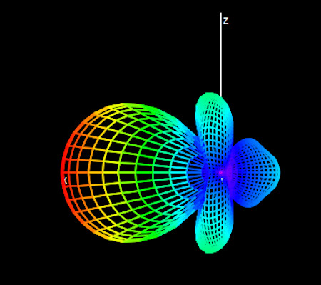
The calculated free-space maximum gain of 9.4 dBd at 50.2 MHz agrees with the M2 specifications. The free-space elevation gain profile (ie. looking from the side) with ARRL log scaling is shown in the left figure below.
In my setup, the antenna is deployed in several acres of open pasture, so some ground gain is to be expected. I use the installed height of 52 ft over a ground-plane of coastal, sandy soil with dielectric constant of 10 and conductivity of 0.002 S/m. The elevation gain pattern with ground reflection is in the right plot below. Maximum gain is found to be 14.85 dBd (17.0 dBi) into the primary lobe with a takeoff angle of 5 degrees. The calculated 3-dB azimuthal beamwidth for the first lobe is ± 22.5 degrees. Other lobes are at elevation angles 16 and 28 degrees.
|
|
Large Vertical Array for 50 MHz: 4 x DSE3 by Directive Systems
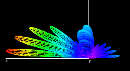
The large vertical array (LVA) is an arrangement of stacked yagi beams pointing in a fixed direction. Stacking short yagis results in a very wide beamwidth but with the gain of a single antenna having a much longer boom. The Directive Systems DSE3-50LVA-4 design stacks 4 of their 3-element rear-mounted, short 6-meter antennas at 10 ft separation increments.
The following simulation places the individual antennas at heights of 15, 25, 35, and 45 ft over sandy, coastal soil. The azimuthal plot on the left reveals a 3-dB beamwidth of ± 32.5 degrees or about 30 percent wider than the 6M5X at 52 ft. The elevation plot shows peak gain of 15.91 dBd at 50.2 MHz with a broad lobe centered at an 8.5 degree takeoff angle.
|
|
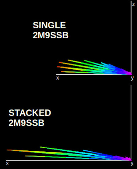
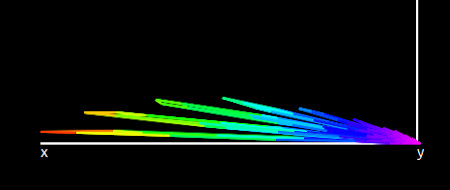
2M9SSB 9-element 2-meter yagi by M2
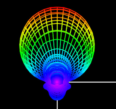
My stack of 2 x 2M9SSB antennas for 2m is about 9 wavelengths above ground. Simulations can be used to see the effect of stacking: comparing a single yagi at 52 ft to the stacked arrangement with a second identical antenna mounted 9.5 ft above it. Results are shown below. These plots use linear scaling to better depict changes to the radiation lobes. The images are scaled in proportion to their relative gain. A single yagi yields a maximum gain of 17.43 dBd (19.58 dBi) at 144.2 MHz in the primary lobe. Adding the second beam increases the maximum gain to 19.7 dBd (21.85 dBi) and compresses the radiation lobes toward the horizon. The primary lobe is at 5 degrees. Although sharp nulls are evident, they are spaced by 1--2 degrees and should smear out in the far-field due to diffraction.
No significant change to the beamwidth in the azimuth (± 17.5 degrees) is observed, which is the expected behavior for vertical stacking. Very little difference was found comparing a perfect ground to coastal sandy soil.
|
2M5WL 17-element 2-meter yagi by M2
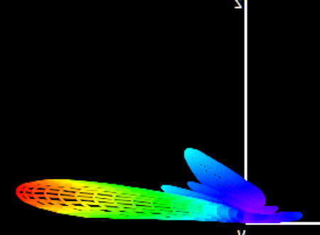
The M2 advertising literature claims that stacking 2 x 2M9SSB antennas produces equivalent gain to their single 17-element yagi design on a 33 ft boom. Modeling the 2M5WL in free-space shows 14.5 dBd gain at 144.2 MHz with a horizontal beamwidth of ± 13.5 degrees, consistent with the M2 specifications.
Modifying the simulation to place the antenna 52 ft above a perfect ground produces the azimuthal gain plot shown below (linear scaling). Ground reflection increases gain to 20.45 dBd with the same ± 13.5 degree 3 dB beamwidth. The ∼ 0.7 dB higher gain that the long yagi generates compared to the stack comes with a 23 percent reduction in beamwidth. In addition, the takeoff angle of the primary lobe is under 2 degrees, ie. concentrated at the horizon. This may not be optimal for working terrestrial DX and especially meteor scatter, but will make it a better candidate for EME with elevation angle control.
|
The custom .nec files used for these simulations are available on github. I did not include the T-match structure so the calculated VSWR will not be correct.