My 6m station has three separate antenna systems: 1) a rotatable 5-element beam at 53 ft, 2) a fixed position LVA pointing northwest, and 3) a fixed position LVA pointing northeast. Each antenna system has an independent feedline with individual lightning arrestors in the shack. The antennas are selected using two Tohtsu CX-600NL SPDT relays that are capable of handling the full amplifier output power. The arrangement is shown below right.
|
|
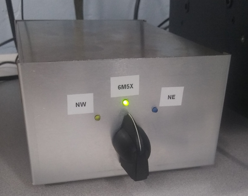
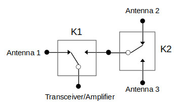
When both relays are de-energized, Antenna 1 is selected as the default. When K1 is on and K2 is off, Antenna 2 is connected. When both K1 and K2 are driven, Antenna 3 is selected. The relays are located next to the amplifier in the shack. Coil resistance is 75 ohms and the required drive is 160 mA at 12 VDC.
A simple SP3T antenna switch is possible, but I wanted to make the system fail-safe to prevent hot-switching. To do this, I had to interface the antenna selector to the transceiver/amplifier PTT line. Whenever PTT is low, the station is in transmit so the relays must remain in their previously selected state; any change to the 3-position front panel switch is ignored. There are different ways to accomplish this, but I decided to build a control circuit using a Texas Instruments MSP430 development board. The MSP430 microcontroller is intended for long-life battery-powered applications. Although power is not an issue here, I had a MSP-EXP430F5529LP Launchpad left over from a previous project and figured it could be put to good use as a smart switch controller. An Arduino or any variety of low-cost microcontroller would work just as well.
|
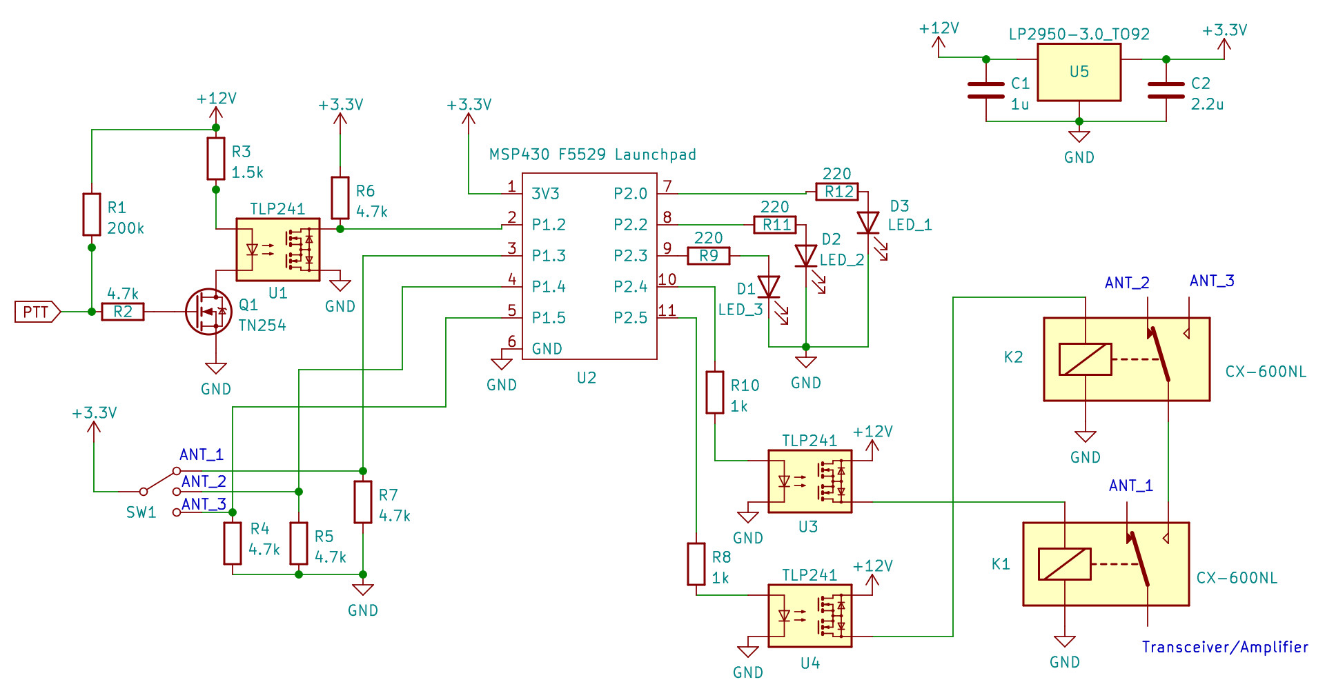
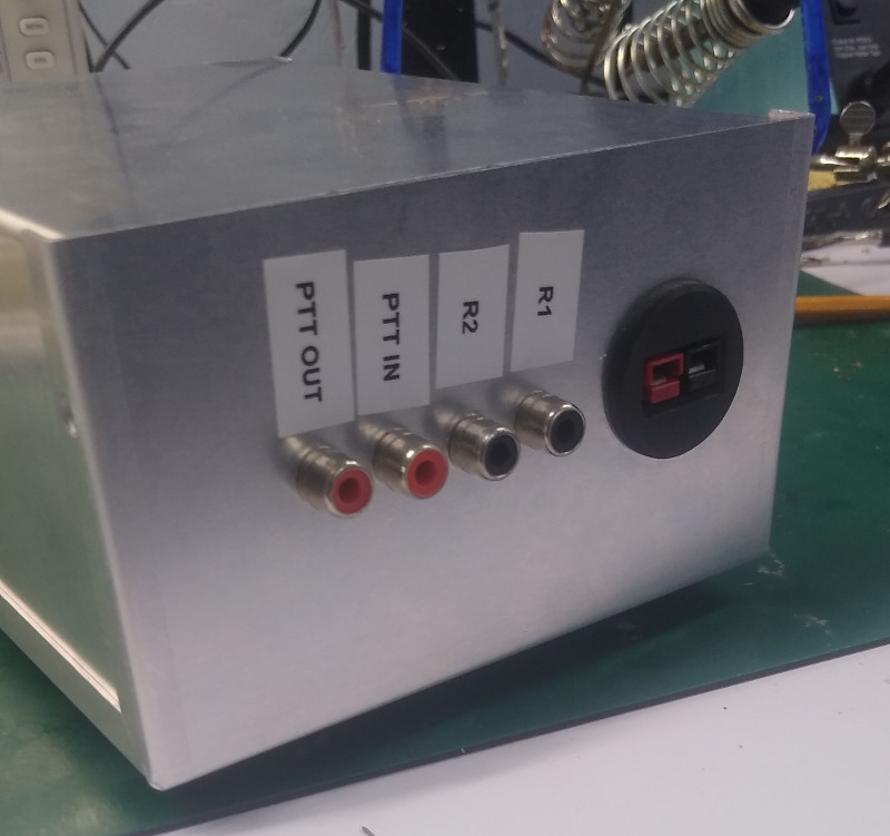
The control unit is in a metal box separate from the relays and located at the operating position. The relays are activated on two RCA speaker cables. I power the switching circuit from the same 13.8 VDC supply used for the transceiver. The Launchpad requires 3.3 VDC, however, so a TI LDO voltage regulator (LP2950CZ-3.3, TO-92 package) reduces the power supply voltage to the needed level. To isolate the microcontroller from the 12V circuitry, optically-coupled MOSFETs (Toshiba TLP241A) are used for the relay drivers and PTT switch. These transistors can handle the continuous coil current without need for a drain resistor.
I discovered that the infrared LED on the opto-isolator U1 drew enough current that it would continuously pull down the PTT line, keeping the amplifier keyed. This was fixed by placing a high input impedance n-channel enhancement FET (Q1: Microchip TN2540N3) in series with the input. A 200k pullup resistor holds the PTT line high in the default RX state.
|
|
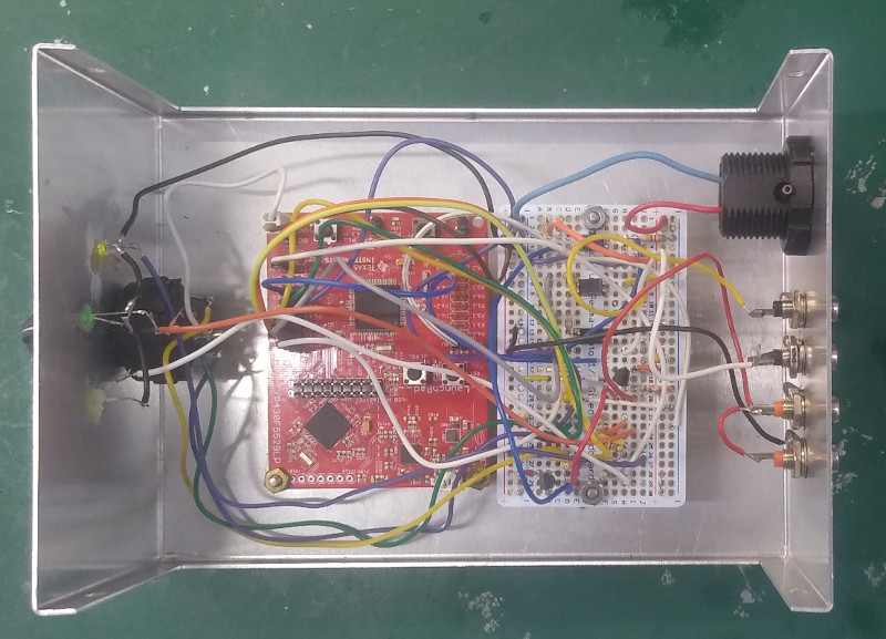
Front panel LEDs are entirely optional, but the Launchpad has many I/O ports available so I opted to use them for this purpose. With the exception of R3, none of the passive component values are critical. The Launchpad and circuit board fit comfortably in a 5 x 7 x 3 inch project box. Microcontroller firmware is written in C and linked here.